banner


Can The Mac Mini Hard Drive Be Repaired

Introduction

Utilise this guide to replace the hard drive in your difficult-drive-just or Fusion Drive Mac mini Late 2022.

This guide was made with a Fusion Drive Mac mini. If your Mac mini only has a difficult bulldoze, skip the steps about the PCIe SSD and its connector.

  1. The bottom cover is clipped onto three screw posts.

    • The bottom cover is clipped onto iii screw posts.

    • Pry near, but not right on the screw posts.

  2. Use the plastic opening tool to pry the bottom cover up off of the Mac mini. Use the plastic opening tool to pry the bottom cover up off of the Mac mini. Use the plastic opening tool to pry the bottom cover up off of the Mac mini.

    • Use the plastic opening tool to pry the lesser cover up off of the Mac mini.

  3. Lift and remove the bottom cover. Lift and remove the bottom cover.

    • Elevator and remove the bottom cover.

  4. Remove the following TR6 screws from the antenna plate:

    • Remove the following TR6 screws from the antenna plate:

    • Iii 4.one mm screws

    • Iii i.9 mm screws

  5. Do not completely remove the antenna plate; it is still connected to the Mac mini by an antenna cable. With the I/O ports facing you, flip the antenna plate to the right to allow access to the antenna cable connector.

    • Do non completely remove the antenna plate; it is still continued to the Mac mini by an antenna cable.

    • With the I/O ports facing y'all, flip the antenna plate to the correct to allow access to the antenna cablevision connector.

  6. Remove the single 3.4 mm T6 screw and washer from the antenna cable.

    • Remove the single 3.4 mm T6 screw and washer from the antenna cable.

    • Be careful not to lose the washer when removing the screw.

  7. Use the point of a spudger to lift the antenna connector straight up off its socket on the airport card. Use the point of a spudger to lift the antenna connector straight up off its socket on the airport card.

    • Utilize the point of a spudger to lift the antenna connector directly up off its socket on the drome card.

  8. Carefully pull the antenna cable out from the gap between the power supply and case. Carefully pull the antenna cable out from the gap between the power supply and case.

    • Carefully pull the antenna cablevision out from the gap between the power supply and example.

  9. Remove the antenna plate from the Mac mini.

    • Remove the antenna plate from the Mac mini.

  10. Remove the two 12 mm T6 screws from the fan.

    • Remove the 2 12 mm T6 screws from the fan.

    • Loosen the 27 mm T6 captive spiral.

  11. The fan connector is trapped under the edge of the fan and cannot be disconnected until the fan is moved. Do not attempt to remove the fan entirely. Lift the fan straight up to free the captive screw from its hole in the logic board.

    • The fan connector is trapped nether the edge of the fan and cannot be disconnected until the fan is moved.

    • Do non attempt to remove the fan entirely.

    • Lift the fan direct upward to free the captive screw from its hole in the logic lath.

    • Pull the fan away from the SSD until you lot can easily access the fan connector.

  12. Use the point of a spudger to lift the fan connector straight up out of its socket on the logic board. Use the point of a spudger to lift the fan connector straight up out of its socket on the logic board.

    • Use the point of a spudger to lift the fan connector directly upwards out of its socket on the logic board.

  13. Remove the fan from the Mac mini.

    • Remove the fan from the Mac mini.

  14. Remove the 2.6 mm T6 screw securing the SATA cable connector bracket.

    • Remove the ii.vi mm T6 spiral securing the SATA cablevision connector subclass.

  15. Remove the SATA cable connector bracket. Remove the SATA cable connector bracket.

    • Remove the SATA cablevision connector bracket.

  16. Use the flat end of a spudger to lift the SATA cable connector up off of its socket on the logic board. Use the flat end of a spudger to lift the SATA cable connector up off of its socket on the logic board.

    • Use the apartment end of a spudger to lift the SATA cable connector up off of its socket on the logic board.

  17. Use the tip of a spudger to disconnect the IR sensor cable connector by prying it straight up from its socket. Use the tip of a spudger to disconnect the IR sensor cable connector by prying it straight up from its socket.

    • Use the tip of a spudger to disconnect the IR sensor cable connector past prying it directly upwards from its socket.

  18. The following three steps only apply to Mac minis equipped with a PCIe SSD. Skip the next three steps if your Mac mini only has a hard drive.

    • The following 3 steps only employ to Mac minis equipped with a PCIe SSD. Skip the side by side iii steps if your Mac mini just has a hard drive.

    • Remove the two 2.6 mm T6 screws securing the PCIe SSD cable bracket.

  19. Remove the PCIe SSD cable bracket. Remove the PCIe SSD cable bracket.

    • Remove the PCIe SSD cable bracket.

  20. Lift the PCIe SSD connector up off its socket. Lift the PCIe SSD connector up off its socket.

    • Lift the PCIe SSD connector upwards off its socket.

  21. Remove the single 16 mm T6 screw securing the logic board.

    • Remove the single 16 mm T6 screw securing the logic board.

    • To remove the logic board, the ii cylindrical rods of the Mac mini Logic Lath Removal Tool must be inserted into the holes highlighted in red. Inserting instruments into any logic board holes other than the ones highlighted in red may destroy the logic board.

    • Insert the Mac mini Logic Board Removal Tool into the two holes highlighted in red. Be sure the rods make contact with the instance under the logic board before proceeding.

  22. Carefully pull the tool toward the I/O board. The logic board and I/O board assembly should slightly slide out of the outer case. Cease prying when the removal tool makes contact with the opening in the rear case. Remove the Mac mini Logic Board Removal tool.

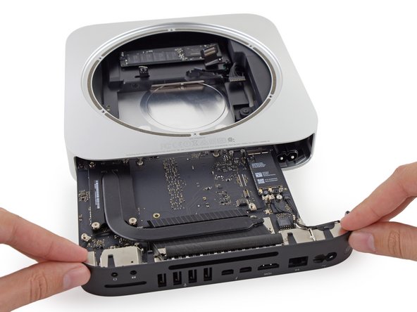
    • Carefully pull the tool toward the I/O lath. The logic lath and I/O board associates should slightly slide out of the outer case.

    • Stop prying when the removal tool makes contact with the opening in the rear instance.

    • Remove the Mac mini Logic Board Removal tool.

  23. Pull the DC-In cable connector straight out of its socket on the logic board. Pull the DC-In cable connector straight out of its socket on the logic board.

    • Pull the DC-In cablevision connector direct out of its socket on the logic board.

  24. Carefully slide the logic board assembly out of the Mac mini, minding any cables that may get caught. Carefully slide the logic board assembly out of the Mac mini, minding any cables that may get caught.

    • Carefully slide the logic lath assembly out of the Mac mini, minding any cables that may get defenseless.

  25. The AC-in socket is secured with a small metal retaining clip. Use tweezers or your fingers to pull the clip away from the AC-in socket, and remove it from the Mac mini. When replacing the clip, push it in until it stops—it should be secure even if there is no audible click.

    • The AC-in socket is secured with a pocket-sized metal retaining clip.

    • Use tweezers or your fingers to pull the clip away from the Air conditioning-in socket, and remove information technology from the Mac mini.

    • When replacing the prune, push it in until it stops—it should be secure even if in that location is no audible click.

  26. To free the power supply from the case, grab the AC-In connector, which acts like a latch. Rotate the AC-In connector 90 degrees counter-clockwise. Rotate the AC-In connector 90 degrees counter-clockwise.

    • To free the power supply from the case, grab the AC-In connector, which acts like a latch.

    • Rotate the Air-conditioning-In connector 90 degrees counter-clockwise.

  27. The AC-In latch should fit into the groove above it in the case.

    • The Air-conditioning-In latch should fit into the groove above it in the case.

    • During reassembly ensure the power supply is inserted far enough into the example that the latch will appoint with the groove.

  28. Remove the 8 mm T6 screw securing the power supply.

    • Remove the 8 mm T6 screw securing the power supply.

  29. Slide the power supply out of the mini, minding any cables that may get caught. Slide the power supply out of the mini, minding any cables that may get caught.

    • Slide the power supply out of the mini, minding any cables that may get defenseless.

  30. Remove the single 8 mm T6 screw securing the drive tray.

    • Remove the single viii mm T6 spiral securing the drive tray.

  31. Lift the drive tray up out of the Mac mini. Lift the drive tray up out of the Mac mini. Lift the drive tray up out of the Mac mini.

    • Elevator the drive tray up out of the Mac mini.

  32. Remove the four (two on each side) 6.5 mm T8 screws securing the hard drive to the drive tray. Remove the four (two on each side) 6.5 mm T8 screws securing the hard drive to the drive tray.

    • Remove the four (ii on each side) 6.5 mm T8 screws securing the hard drive to the drive tray.

  33. Lift the hard drive up and remove it from the drive tray. During reassembly, be sure to thread the hard drive cable through the slot in the drive tray. During reassembly, be sure to thread the hard drive cable through the slot in the drive tray.

    • Lift the hard bulldoze up and remove it from the drive tray.

    • During reassembly, be sure to thread the hard drive cable through the slot in the bulldoze tray.

  34. Lift up the ribbon cable and carefully peel away the black tape underneath. It secures the SATA cable connector to the PCB of the hard drive. Failing to remove the tape will almost surely cause the contacts soldered to the flex cable to rip from the connector housing, as the retention force of the contacts in the housing is quite low. Pull the SATA cable connector straight out of the hard drive. Carefully peel off the two black, square-shaped sticky pads (one visible in picture) from the corners of the hard drive, and stick them to your new hard drive in the same locations.

    • Elevator up the ribbon cable and advisedly peel abroad the black tape underneath. It secures the SATA cablevision connector to the PCB of the hard drive. Declining to remove the record will nigh surely crusade the contacts soldered to the flex cable to rip from the connector housing, as the retention forcefulness of the contacts in the housing is quite low.

    • Pull the SATA cable connector straight out of the hard bulldoze.

    • Carefully peel off the 2 black, square-shaped viscid pads (one visible in motion-picture show) from the corners of the difficult bulldoze, and stick them to your new hard drive in the same locations.

Conclusion

To reassemble your device, follow these instructions in opposite society.

Team

Embed this guide

Choose a size and copy the lawmaking below to embed this guide equally a minor widget on your site / forum.

Preview

Source: https://www.ifixit.com/Guide/Mac+mini+Late+2014+Hard+Drive+Replacement/32815

Posted by: jaredfroneam1996.blogspot.com

0 Response to "Can The Mac Mini Hard Drive Be Repaired"

Post a Comment

Iklan Atas Artikel

Iklan Tengah Artikel 1

Iklan Tengah Artikel 2

Iklan Bawah Artikel